Fission Track :Laboratory Personal Protective Equiptment (PPE) Requirements
- SUITABLE CLOTHING must be worn, long trousers are recommended for all staff and students.
- PROTECTIVE CLOTHING must be worn for protection in case of fire or chemical spillage. It is usually a knee-length white coat, but for some operations more elaborate protection may be required.
- SOUND FOOTWEAR must be worn. Thongs, sandals, and other open-style shoes are PROHIBITED.
- SAFETY GLASSES are compulsory when cutting glass slides. Glasses must conform to Australian standard 1337.
- The storage and/or consumption of FOOD and DRINK in the laboratory is PROHIBITED.
- VISITORS to the laboratory must comply with the PPE requirements.
- Laboratory coats and other protective clothing are not to be worn in eating and "tea" areas.
- A radiation monitor must be worn when working in the fission track sample preparation laboratory.
- All accidents/incidents must be reported to the School Safety Officer, as soon as possible.
Working in the fission track laboratory
The School of Earth Sciences has established a “Licence” system whereby students wishing to use the fission track sample preparation and counting laboratories are first trained in the relevant procedures by the Laboratory Supervisor before being issued with a licence valid for the duration of the work planned. This licence permits the student/user to conduct specified work in the fission track sample preparation and counting laboratories only, and generally during normal working hours as described in the licence itself, unless otherwise arranged with the Laboratory Supervisor.
Research workers should try as far as possible to organise their experimental work so that hazardous operations are carried out WITHIN NORMAL WORKING HOURS. When such operations have to be performed outside normal working hours, the operator must first make sure that a SECOND PERSON is available within the IMMEDIATE VICINITY throughout the experiment, so as to provide help, if needed. The ‘out-of-hours’ diary outside reception on level 4 must be completed if work is being conducted outside normal working hours.
Radiation Protection
All users of the fission track laboratory will at some stage handle irradiated material. Users of the laboratory are required to wear film badges (TLD’s) at all times. These are organised through the Laboratory Supervisors and are monitored and recorded by the Australian Radiation Laboratory (ARL). It is extremely important for all users to familiarise themselves with the hazards attached to the handling of irradiated material. The safety of each person ultimately depends on the good work practices of themselves and of all those around them. Given below is the useful background information
The electromagnetic spectrum contains radiation of wavelengths \(10^{-12}\) to \(10^{4}\) cm. The spectrum ranges from cosmic and gamma radiation (\(10^{-12}\) to \(10^{-8}\) cm) through x radiation, ultraviolet, visible, infrared and microwaves to radio frequencies of \(10^{2}\) to \(10^{4}\) cm. Exposure to radiation can cause genetic defects or cancer. Cosmic radiation (background for the Earth) is approximately 5 x \(10^{-4}\) Sievert per year (in some parts of the world 0.12 Sievert has been recorded).
Ionising radiation
This radiation is capable of producing ions directly or indirectly in its passage through matter. It occurs in both nature and in material generated within a nuclear reactor. Instability in nuclei (or radioactivity) is due to an unfavourable neutron to proton ratio in that nucleus. These nuclei achieve stability by emitting ionising radiation (through from just one to many changes in structure) and it is this which concerns us in radiation protection. The main species of ionising radiation are described below.
X-rays: These are produced when a fast moving stream of electrons or charged particles interact with matter. Electrons are ejected from inner shells of target atoms and when electrons from outer shells fall back to take their place fall energy in the form of X-rays is emitted. In an X-ray tube the accelerating voltage can be varied, usually from 10 kv to 100 kv, so the wavelength of the X-rays can be varied. X-rays can be generated in any equipment where a fast-moving electron beam or steam of charged particles interacts with matter (e.g. X-ray spectrometer, electron microscope, mass spectrometer).
Gamma-rays: These are physically similar to X-rays but of shorter wavelength. They are emitted when most radioactive changes take place. The gamma ray (or photon) has no mass or electric charge. Its energy is related to its frequency. Gammas produce very little ionisation through a medium and therefore the radiation is very penetrating. Gamma rays produced during the decay of \(^{22}Na\) (half-life of 2.6 years) and \(^{24}Na\) (half-life of 15 hours) produced by irradiation of the soda-lime glasses of apatite mounts and standards glasses are of concern in the fission track laboratory. \(^{22}Na\) is a nuclide of high radiotoxicity with an effective half-life in the body of 10 days. Appropriate shielding and safe storage is required
Alpha-rays: These are streams of alpha particles or positive helium nuclei. They have high energy but because of their mass (more than 7000 times that of an electron) they are poorly penetrating (range of millimetres in air depending on their energy). Alpha rays are generally not of concern in the fission track laboratory.
Beta-rays: These are electrons emitted by radioactive nuclides. They are more penetrative than alpha rays but with moderate powers of ionisation. An electron is generally produced in unstable nuclei by the transformation of a neutron into a proton and an electron, with the electron being ejected from the nucleus. Beta rays are generally not of concern in the fission track laboratory.
Neutrons: Uncharged but capable of initiating radioactive disintegration. Neutrons are not of concern in the fission track laboratory.
Bremsstrahlung: A form of X-radiation produced by the interaction of beta’s with matter.
Positrons: similar to electrons, but with a positive charge and short life.
The effect of ionising radiation on humans
Humans are constantly exposed to ionising radiation in the form of cosmic radiation and natural radioactivity in the environment and in the body, and to man-made radioactivity from fallout, X-rays, etc. The effect of radiation on humans can be separated into two distinct types; internal and external. External radiation is obviously that which strikes the body from the outside, e.g. an X-ray. Internal radiation is a far more insidious danger than external radiation because the radiation, which is capable of high degrees of ionisation (with poor penetrating power) such as alpha particles, can now interact directly with cellular material, etc.
Standards
The Australian NHMRC have set radiation protection standards and set dose limits, in order to minimise the chance of such an occurrence. For this reason, radiation workers wear monitors to measure exposure rates. The "Effective Dose" is used in describing radiation exposure and calculated from the absorbed dose to the skin and modified by factors such as the sex of the wearer, and the energy and type of potential radiation exposure, etc.
The Thermoluminescent dosimeter (TLD monitor). This is the film badge normally worn at chest or hip level. The accumulated doses are determined by measuring the light output of the TLD card when it is heated through a specific heat cycle. These are supplied to radiation workers.
Units
Becquerel (Bq)-unit of activity = one disintegration per sec.= 2.7027 x \(10^{-11}\) Curie (Ci). Dose equivalent = factored absorbed dose (modified to take into account the type of radiation). Measured in Sieverts. For gamma rays an absorbed dose of 1 Gray (Gy) gives a dose equivalent of 1 Sievert (Sv) whereas for alphas it is 20 Sievert (Sv). Previously, the dose equivalent unit was the rem. (1 rem = 0.01 Sv = 0.01 rad).
Dose limits
For radiation workers, the dose limit is 20 millisievert/year (mSv/yr).
Rock Crushing and Mineral Separation for Fission Track Dating
1. Introduction
Rock crushing and mineral separation for fission track dating is primarily aimed at the recovery of three minerals: apatite, zircon and sphene. These three minerals are the most widely used uranium-bearing accessory phases in fission track dating as they are present as primary minerals in most igneous and metamorphic rock types and as detrital constituents of sandy sediments. The annealing behaviour of other minerals which can potentially be used in fission track studies most notably epidote group minerals and some types of garnets, are not well understood and thus they are not, as yet, generally suitable for rigorous study. The following procedure was developed over many years by many contributors in the Fission Track Laboratory of the School of Earth Sciences, University of Melbourne. For the most part the mineral separation procedures followed are standard, but they have been adapted and modified to give maximum yield of the required minerals in the shortest possible time. Where possible, personal recipes and short cuts have been included but many are personal preferences unique to individual workers and may not be suitable for everyone. Many of the finer points of technique are not easy to describe, thus there is no substitute for the actual hands-on acquisition of these skills in a functioning laboratory. The various steps used for mineral separation are shown as a flow chart in Figure A.1.
Important: Absolute cleanliness at each stage of rock crushing and mineral separation is of paramount importance. The final fission track results are only as good as the attention given to prevent possible contamination by foreign mineral grains.
2. Rock Crushing
Depending on the rock type, samples will typically range in weight between ~500 g to 3 kg. Hard rock samples must first be reduced to a size suitable for the grinding machine in use. Large samples should be reduced in size with a sledge hammer or hydraulic splitter (Figure A.2), followed by processing through a large laboratory Rocklabs® jaw crusher (Figure A.3).
2.1 Initial crushing: Jaw Crusher
- a) It is advisable to remove any weathered rind from outcrop samples with the diamond saw, wire brush or hydraulic splitter prior to crushing, to guard against possible contamination by exotic mineral grains adhering to soil, etc.
- b) Make sure jaw crusher is absolutely clean. Use compressed air (in suitably exhausted environment) and wash with alcohol if necessary. Never leave equipment water-wet as rusting is rapid.
- c) Crush a small amount of the sample in the jaw crusher and discard.
- d) Crush the required amount of sample down to ~10 to 20 mm diameter chunks. The amount of sample required depends upon the mineral content of the rock type involved and can vary between tens of grams and tens of kilograms. A few hundred grams of washed and sized material is usually sufficient for granitic rocks.

Figure A.1:Flow chart of apatite mineral separation. Qtz=quartz, Feld=feldspar, Kspar=potassium feldspar, Mag=magnetite, Bio=biotite, Hbl=hornblende, Pyx=pyroxene, ilm=ilmenite, Epi=epidote, Gar=garnet, Sp=sphene, Bar=barite, Fl=fluorite, ss=side slope, fs=forward slope.

Figure A.2:Hydraulic splitter
Grinding Mill
A wide variety of crushing and grinding equipment can be used to further reduce the particle size and disaggregate grains. Our preference is for a Van Gelder® 200 Disc Pulveriser with rotating plate mill fitted with hardened steel plates (Figure A.4).
- Make sure the grinding mill is absolutely clean.
- Adjust the grinding mill to produce material less than about 500 um in diameter. This will vary depending on the type of mill used, the degree of wear on the grinding plates, the hardness of the rock, etc. With experience it is often possible to skip the following sieving step (2.3).
- Put through a small amount of sample and discard.
- Process the rest of the sample. Generally crush all sample until it passes 500 um then wash away the fines (2.3.e). In some cases, particularly for graywackes, samples may have to be put through the grinder several times to obtain the required sizing.

Figure A.3:Jaw crusher

Figure A.4:Van Gelder® 200 Disc Pulveriser
2.3 Sieving
Sieving is not always necessary. With experience one gets to know how fine to grind, and washing the sample will remove the fines.
- a) Select sieves to give a fraction between about 90 and 500 um. Grains less than about 90 um are generally too small for fission track dating and fractions larger than ~500 um contain too many composite grains.
- b) Make sure sieves are absolutely clean.
- c) Complete the sieving, possibly in several lots.
- d) Discard the < 90 um fraction and retain > 500 um for possible reprocessing if needed.
- e) Wash the 90 to 500 um fraction by decanting suspended fines in water. Use a large plastic bucket (10 litre) or a flat aluminium tray (approx. 330 x 280 x 60 mm is suitable).
- f) Allow the washed sample to dry overnight (at ~50°C) in a clean dustless area on shelves in the Contherm® Digital Oven./li>
3. Mineral Separation
Separation of the required uranium-bearing accessory minerals is achieved by exploiting differences in mineral density with heavy liquids, and a Gemini® table (Figure A.5), and differences in magnetic susceptibility with a Frantz® isodynamic magnetic separator (Figure A.6).

Figure A.5:Gemini® table
3.1 Gemini® table
If a Gemini® table is available it can greatly enhance the speed with which large samples (several kilograms) can be processed and cuts down considerably on the volume of heavy liquid required. The sample can be taken from the either the grinding (2.2) or sieving steps (2.3) and placed directly into the auto-feed hopper of the Gemini Table. Prior washing of the sample is not necessary. The shaking motion of the table, the water feed and the side and forward slope can be adjusted to maximise the heavy fraction. This results in a much reduced sample size for the next steps, which is especially advantageous in the heavy liquid processing.
When finished make sure area is clean and table is ready for use by the next person.
3.2 Ferro-magnetic mineral removal
- a) Make sure all apparatus - glassware, Frantz® isodynamic magnetic separator, etc, is absolutely clean.
- b) Remove ferromagnetic minerals - chiefly magnetite and some biotite and magnetic particles from the grinding plates with either a hand magnet or pour the sample through a paper funnel attached to the vertical Frantz (at full current). After the non-magnetic fraction has been collected beneath the funnel in a large beaker or in a tray, insert another beaker to catch the ferromagnetic phases adhering to the paper funnel, and turn off the current.
- c) Remove mafic phases (biotite, hornblende, pyroxene) - the next step is to use the vertical feed attachment for the Frantz at 0.4A (current setting) to remove mafics. As much mafic material as possible should be removed magnetically at this stage to reduce the amount of heavy material sinking along with the target minerals in the heavy liquid. Too much material sinking in the heavy liquid invariably carries down a lot of lights with it, which impedes a clean separation.
Note: Extremely magnetic samples are sometimes encountered. These should be treated slowly in small magnetic increments so as not to trap any non-magnetic material, i.e. 0.2A, 0.4A, 0.8A, etc.
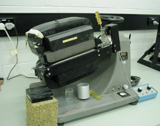
Figure A.6:Frantz® isodynamic magnetic separator
3.3 Heavy liquid separation
Two types of heavy liquids of different specific gravity have been traditionally used, ie Tetrabromoethane (TBE) and Di-iodomethane (DIM). Both are dangerous and any amount, including small drops should be washed from gloves, skin etc. immediately with alcohol and water. TBE, of specific gravity ~2.95 g/cc, is particularly toxic and has now largely been replaced by the non-toxic Sodium Polytungstate (SPT).
Important:
- Laboratory clothing and safety glasses are recommended.
- No smoking anywhere in the laboratory.
- No eating or drinking in the laboratory.
- Use of semi-permanent and/or disposable rubber gloves is required at all times.
- Report all spills.
- DIM separations should be carried out in properly constructed fume cupboard.
- Heavy liquids are expensive and should always be recovered.
- Clean work space when you have finished.
- a) SPT is sold as a salt and this can be made up to the required density by dissolving in distilled water. A SPT solution with a density of ~2.96 g/cc can be produced by dissolving ~1kg of salt in ~250 ml of distilled water. The density can be easily lowered by adding distilled water or raised (to a maximum of 3.1 g/cc) by evaporation at room temperature or very gently heating. When mixing it is best to add the salt slowly with continuous vigorous mechanical stirring.
- b) Check liquid density is ~2.85 g/cc using the hydrometer.
- c) Make sure all funnels, flasks, etc. are absolutely clean.
- d) Set up apparatus as in Fig. A.7. Special separating funnels with open tops 125 to 150 mm in diameter and with large tap openings (approx. 10mm) are ideal for large volumes of material.
- e) Close taps and fill the separating funnel with the material from step 3.2 to within about 25 mm of the top with SPT.
- f) Stir vigorously with a glass rod and then insert a mechanical stirring device and start at slow speed (about 40 rpm). Stir near top of liquid. A suitable stirring rod can be made of glass with a 50 mm long "T" cross piece. Carefully monitor the stirring speed in the initial stages as it can increase rapidly, spilling out over the edges of the funnel, as the rock/liquid "mush" loses viscosity with turbulence. Allow stirring to continue for 30-60 minutes or until mineral settling is complete. Problem samples may take repeated periods of stirring followed by quiet settling for efficient heavy mineral removal. Cover top of funnel with plastic wrap to reduce evaporation
- g) When all the heavy mineral constituents are believed to have settled out, place a conventional funnel with single or double thickness of coffee filter paper (double thickness produces a clearer filtrate) with a retaining ring over the edge of the paper and a filter flask under the separating funnel. Note SPT is a somewhat viscous solution so its filtration rates are much slower than say TBE, but coffee filters provide more rapid filtration rates than conventional laboratory filter papers. Carefully take off the settled heavy mineral fraction - very slowly at first to avoid splashing. Keep heavy filtered SPT for further use.
- h) Next, remove the filter funnel from the flask and place it in the “SPT washings" filter flask. Wash the heavy mineral fraction thoroughly with deionised water until all traces of SPT are removed. It often helps to allow the mineral ‘cake’ to soak in water for a few minutes before turning on the vacuum. Note: Heavy fraction may need washing in an ultrasonic bath to remove fine Ca tungstate precipitates by decanting if these are formed. Rinsing with acetone or alcohol may speed up the drying process.
- i) Dry the filter paper and heavies under a low temperature heat lamp.
- j) When dry, transfer the heavy minerals to a clean paper and store in a clean, labelled vial.
- k) Place the used coffee filters in a clearly labelled waste plastic bag kept in the fume cupboard for later proper disposal.
- l) Recover and wash the light fraction. Place a large Buchner-type funnel with coffee filter paper in a "clean SPT" filter flask. Stir sample with a glass rod to get lights into suspension and turn on the vacuum. Press down on the paper until the paper seals well on the carrier plate of the Buchner funnel or else grains will escape into the clean SPT. Open the stopcock about l/3 and draw off the SPT and lights, keep stirring until the funnel is drained. If you don't stir you will find the material clogs the funnel. Leave on the vacuum for 5 to 10 minutes or until most of the SPT is in the flask. Note: Be especially careful not to let the liquid go above the vacuum outlet of the flask, so if bubbles form in the SPT during filtration. Break vacuum by releasing hose. Do not let SPT boil or overflow.
- m) Transfer the Buchner funnel containing the light fraction to a filter flask dedicated to "SPT washings". Wash with deionised water until SPT is removed. As in step 3.3.h soak the light fraction before applying the vacuum. Leave on vacuum until only water appears to be coming through.
- n) Dry the light fraction and either place in sealable plastic bag for other studies or discard./li>
- o) Place the used coffee filter paper in the waste plastic bag.
SPT Recovery and Clean-Up
As the SPT solution is originally made up from a salt it is also possible to recover most of this material for subsequent use, with the following procedure.
- i) All washings from large funnel and flasks should be allowed to stand overnight in large measuring cylinders. The following day the washings can be filtered through a coffee filter paper over a sheet of No. 2 filter paper, using a retaining ring and nylon filter paper support mesh. Rinse the sediment into washings with deionised water. Rinse measuring cylinders into one cylinder to stand.
- ii) Pour washings into evaporating pans to evaporate at maximum temperature of 65°C with fan turned on. Allow to evaporate until viscous, but not to dryness.
- iii) Filter cooled concentrate through two layers of coffee filter paper over a support mesh. Rinse filter papers into separate washings flask and pour washings into cylinder to stand. Adjust the specific gravity of the concentrate to 2.85 g/cc.
- iv) Refill rinsing bottles with deionised water and refill both large containers with deionised water.
- v) Wipe up any remaining SPT splashes with deionised water.
3.4 Magnetic separation using the Frantz
- a) Make sure the Frantz is absolutely clean, use compressed air and wipe with alcohol.
- b) Set the Frantz with a forward slope of 10-20° (depending on sample) and a side slope (top towards back) of 10°. These settings can be varied somewhat for special applications when some experience has been gained. Lower side slopes can be used at a later stage for cleaning up the final mineral fractions (see steps 3.7 and 3.8).
- c) Using the mechanical vibrator and a moderate feed rate process the heavy mineral fraction (from 3.3) through the Frantz in a number of steps increasing the current at each stage. The exact number of passes depends upon the nature of the sample and can be varied with experience. After each stage the least magnetically susceptible sample is reprocessed. Four passes using current (A) settings of 0.4A, 0.8A, 1.2A and full-scale (1.6A) are usually adequate for sphene bearing samples. Three steps can be used if no sphene is present in the 0.4A or 0.8A fractions. Minerals that typically behave magnetically at various current settings are as follows:
- (1) 0.2-0.3A: Minerals including remaining biotite, epidote, clinopyroxene, amphibole, rutile and garnet cross to the magnetic side.
- (2) 0.5A: Sphene may begin to appear on the magnetic side with some amphibole.
- (3) 0.8-1.2A: Sphene, monazite and variable proportions of composite grains with composite magnetic susceptibilities.
- (4) 1.6A (full scale): Usually alot of nondescript rubbish, some weakly susceptible sphene, some zircon and rarely some apatite
- The procedure above typically leaves the following minerals on the non-magnetic side:
- (1) Apatite and zircon - minerals we want!
- (2) Fluorite
- (3) Barite - usually means that the apatite is so diluted that it cannot be recovered efficiently.
- (4) Sulphide and sulphide-composites – this may mean that the apatite is unuseable
- (5) Some dark-coloured spinel (?).
3.5 Second SPT separation
If the “apatite plus zircon” fraction obtained from step 3.4 above is particularly "dirty" it is advisable to perform a second SPT separation in a small separating funnel (100 ml) prior to processing through the DIM (step 3.6). This is usually the case for sulphide-rich samples, which undergo very rapid settling in the first SPT separation leading to the dragging down of some light, non-magnetic material. It is well worth the extra time as it can ensure a reasonably clean apatite fraction from step 3.6.
3.6 Di-iodomethane (DIM) separation
This is usually the final step and results in individual, relatively pure apatite and zircon separates. The separation is carried out in a small separating funnel (100 ml) as used for the second SPT separation (step 3.5 above) if necessary.
- a) Place a small amount of DIM in the separating funnel. A depth of about 25mm is often enough as the sample size is usually only about 0.1-0.4 g at this stage.
- b) Add the sample using a dry funnel as a chute if necessary.
- c) Stir or shake the funnel frequently until settling is complete. Stir frequently and then wash down the stirring rod and the sides of the funnel with DIM from a wash bottle, 3 or 4 times as 12 necessary, to 'wet' the zircons. If this is not done some of the zircons can actually float on the DIM due to a surface tension effect. Leave to settle for a few minutes when finished.
- d) Draw off the heavier zircon fraction into a funnel with a filter paper (No. 4).
- e) Remove the filter-funnel to the "DIM-washings" flask.
- f) Wash the zircon fraction with acetone until it is clean as in step 3.2.
- g) Dry the zircon fraction with a low-temperature heat lamp, transfer to a clean paper, and store in a vial.
- h) Place the used filter paper in the toxic waste plastic bag.
- i) Recover the lighter apatite fraction as in step 3.6.d using a new filter paper.
- j) Transfer the filter paper with the apatite fraction to the "DIM washings" flask and wash with acetone until clean.
- k) Dry apatite with a heat lamp, transfer to a clean paper and store in a vial.
- l) Place the used filter paper in the toxic waste plastic bag.
At this stage it is possible to have acceptably pure apatite, zircon and sphene separates ready for mounting and polishing. "Acceptably pure" depends a little on individual preferences and the particular fission track dating method used, but at least 50% pure is best. Work with sedimentary rocks often results in less pure separates at this stage. These can be cleaned by hand picking under a low-power binocular microscope, if necessary, or sometimes as follows:
3.7 Cleaning the apatite fraction
Reduce the side-slope on the Frantz to +2° (ie top of Frantz towards back) and run at full- scale current. This can clean the sample. Perhaps try +5° first; at slopes less than +2°, some apatite behaves magnetically.
3.8 Cleaning the zircon fraction
Reduce the side-slope on the Frantz to –2° and run at full-scale current. This should be done in gradual steps, i.e. +5° then 0° to –1°, then if still dirty –2°. This procedure can remove sulphides, aluminous sphenes (grothite) and metamict (?) zircons but is not always successful.
The separation procedure should now be complete, with clean apatite, sphene and zircon separates. However, several minerals can still contaminate these fractions as follows:
a) Apatite
1) Barite - generally only occurs in cuttings samples from oil wells where barite has been used in the drilling mud. Barite contamination can be avoided if cutting chips are washed and are big enough so that they can be sieved to retain the >500 um fraction. This fraction is then ground and processed in the usual way. Generally hand picking is impossible as barite will constitute > 95% of the separate.
2) Fluorite - generally occurs in particular granite provinces, e.g. some S-type granites and some tin-granites. It also occurs in sediments derived from such parent granites. Often such an apatite fraction is unworkable as fluorite has almost identical physical properties to apatite and cannot be separated by any of the usual techniques. Apatite often has a very low abundance in such rocks anyway.
3) Sulphide/Quartz composite grains - their composite properties can make these very difficult to handle. Sometimes such separates can be cleaned up using a small nylon sieve of 200 or 300 um hole size as the composites tend to be larger than the apatite. Otherwise hand- picking may be the only way.
b) Zircon
Non-magnetic sulphides - Sieve as for apatite if sulphide is in large grains. Otherwise dissolve sulphide in aqua regia. Place equal volumes of conc. HCl and HNO3 in a small beaker with the grains under a heat lamp. This may need to be done several times to remove all of the sulphides. The recovered grains will then need to be subjected to a another TBE separation in order to move light minerals liberated from sulphide composite grains. A small separating funnel can be used.
c) Sphene
Sphene can separate out over a wide range of Frantz current settings from about 0.5 to 1.2A. It may be contaminated with a variety of minerals, e.g. amphibole and pyroxene. In general, playing around with the current settings, slope and tilt etc. may provide a relatively clean separate. Otherwise handpicking may be used. Another DIM step may also be useful.
Specimen Mounting, Polishing and Ethching Techniques
Introduction
The following is a brief outline of the procedures involved in preparing minerals (a) apatite, (b) zircon and (c) sphene for fission track dating. The description is intended only as a guide and individual variations are often used.
The mineral must first be mounted in a medium, which will support the grains through the later procedures of grinding, polishing, etching and irradiation. Different mediums are used for mounting mineral grains. Apatites are mounted on a glass slide using Petropoxy® (see A.1.h below) and zircon and sphene grains are embedded in teflon. Grinding and polishing are then used to expose an internal surface of the mineral and to remove grinding scratches and surface imperfections, with as little relief as possible, to enable later etching and revelation of fission tracks.
NOTE: Always wash mounts thoroughly before viewing under the microscope- many of the etchants used can corrode the microscope lenses.
A. Apatite
A.1 Mounting
The mounting medium is Petropoxy® 154 - epoxy on a glass microscope slide. Petropoxy® 154 is an epoxide-based mounting medium that has a very low volatility and toxicity. To prepare the epoxy it is necessary to mix the resin with a curing agent. Because the curing agent is highly viscous at room temperature it is necessary to heat the resin to ensure complete mixing.
- a) Add the curing agent to the resin in the ratio of 10:1, e.g. to 5.0 ml of resin, add 0.5 ml of curing agent.
- b) Place a beaker containing the mixture on a hot plate at a normal cure temperature of about 100°C for about 5 minutes (but not longer) – and mix thoroughly with a glass stirring rod.
- c) When mounting specimens make sure glass slide is clean and free of any film.
- d) Label the glass slide by scratching the sample number on the back surface with a diamond or tungsten carbide pen.
- e) Place the glass slide on the hot-plate and highlight an area (~1 cm x 1.5 cm in the centre) where grains will be concentrated, by placing a piece of aluminium foil marked with the required area under the glass slide.
- f) Spread a very thin film of Petropoxy® (just enough to moisten the grain surfaces) over the previously marked area.
- g) Pour a small fraction of apatites (~10 mg) over the epoxy (Figure A.7).
- h) Remove the slide from the hot plate immediately while Petropoxy® is still fluid, and using a binocular microscope and a clean needle evenly distribute the grains over the marked area. This step enables the grains to be separated from each other in an optimal distribution. The significance of this step can be appreciated where the sample quantity is small.
- i) Bring the sample back to the hot-plate and leave for 4-5 minutes to cure the Petropoxy®. While still on the hot-plate, spread a thicker layer of Petropoxy® on top of the previous, now hardened layer, ensuring a greater area is covered.
- For a complete cure the sample should now be left on the hotplate for another 5 minutes.

Figure A.7:Apatite grains in Petropoxy® mount prior to grinding and polishing
A.2 Grinding and Polishing
Grinding and polishing: 600 and 1200 waterproof carborundum abrasive paper on wet a rotating lap and final polishing using 15 and 1 μm diamond paste.
The principal advantage of mounting grains using the method described above is achieved during the subsequent grinding stage. One question often raised during this step is when to stop. In an attempt to expose the maximum number of grains, continuous grinding may lead to loss of some or all grains. Note – it takes only a few seconds to grind the whole mount away. Mounting samples using the method described places all grains regardless of their size and shape on one plane. During grinding, exposure is gradual, with larger grains being exposed first. The risk of losing grains while trying to expose as many as possible is therefore significantly minimised.
The aim of the polishing is to obtain a surface with no imperfections, although a few fractures are always present in some grains. Serious fracturing visible in the grains after polishing usually means that either the epoxy has not hardened properly, enabling the grains to flex, or the grinding has gone too far leaving the grains too thin. If this has occurred it is necessary to make a new mount. A good rule of thumb is to polish until the surface looks free of imperfections and then continue for as long again. This will get rid of any residual strain on the grain surface, which may not be visible.
- a) Lightly bevel edges of upper side of glass slide using 1200 Carborundum paper on a wet rotating lap on the Metaserv ® Rotary Pregrinder (Figure A.8). This prevents tearing of grinding paper and polishing cloth greatly extending their useful life. Place slide in recessed slide holder using water to hold it in.
- b) Grind away excess epoxy with 1200 carborundum paper until approximately 0.5-0.6 mm thick (too much grinding at this stage results in grain fracture). Rotating the grain mount in a direction opposite to the lap movement enhances the quality of the polish. Vary pressure across the holder to correct any tendency towards wedging. Inspect often at this stage.
-

Figure A.8:Metaserv® Rotary Pregrinder
- c) Grind with 600 Carborundum paper until grains are fully exposed. Light pressure in the final stages of this step gives a better finish. Again, a better finish is obtained if the mount is held in a constant orientation on the lap. The thickness will vary considerably, depending on grain size.
- d) Polish with Struers® polishing equipment (Figure A.9>) using 15 um and then 1 um DP- diamond paste on grinding papers attached to rotating laps. Wet with water based lubricant that drips on to the lap via a feeder system. Polishing time is variable for each sample, so needs to be checked periodically. To do this wash mount under a tap, making sure all diamond paste is removed, dry and inspect using reflected light illumination at low-medium power. Repeat d) if necessary.
-

Figure A.8:Struers® polishing equipment
- e) For final polish use grade ‘A’ 0.3 um alumina (Al2O3) slurry in water on a rotating nylon cloth lap on the Metaserv®Rotary Pregrinder. Best results are obtained using a moist lap (not wet) with moderate-hard pressure. If slurry is too thin, polishing will not be efficient. Do not allow the lap to dry out but renew the slurry from a squeeze bottle about every 45-60 sec. Two such cycles are usually sufficient.
- f) Wash under tap, making sure all alumina powder is removed, dry and inspect using reflected light illumination at low-medium power. Repeat e) if necessary.
A.3 Etching– (to be carried out in a fume cupboard)
- a) 3/4 fill a 50 ml beaker with 5N \(HNO_{3}\). Place a 1 litre beaker of water beside the \(HNO_{3}\) etchant to quench the etching.
- b) Using forceps dip apatite mount into acid, ensuring adequate etching by slight movement of slide back and forth. This should be carried out at ambient temperature, i.e. 20°C. Remove after 20 secs (use a timer) and place immediately in beaker of water to stop the etching action. Remember that over or under etching may jeopardise the quality of data. In case of more than one mount, the etching can be done as pairs by holding slides back to back in such a way that grains are exposed to the etchant.
- c) Wash thoroughly under tap, dry and inspect.
- d) If longer etching time is required, wet mount before replacing into acid. This aids the entry of etchant into the partially etched tracks as normally this extra etching will only be for a matter of seconds.
- e) Dry the mount and inspect under the counting microscope to see if tracks are visible. In case extra time required, it will only be a matter of seconds. Dry the forceps each time prior to dipping in the etchant to prevent dilution.
A.4 Trimming
- a) To cut the etched apatite mount to 1 x 1.5 cm size, scribe the back of the slide with a diamond pen at least 2-3 mm away and snap away excess glass. A clean break can be made by flexing the side away from the scored line or by laying the slide on a rigid support (e.g. another slide) up to the scored line and tapping down on the overhanging excess.
- b) Further trimming to final size can be achieved by grinding the edges on the rotating diamond wheel. Smooth the edges by grinding with the 600 grade carborundum paper on a rotating lap, with lap rotating in the direction towards epoxy side of slide.
- c) Clean sample with dishwashing detergent to remove fine glass shards and finger prints. Wash thoroughly with luke warm water to remove all traces of detergent and dry by immersing in alcohol.
B. Zircon
B.1 Mounting
- a) Heat hotplate to 330°C.
- b) Cut PFA teflon sheet into 2 cm x 2 cm squares and wash with alcohol.
- c) Clean 3" x 1" glass slides with breath, alcohol and tissues (one for each mount).
- d) Sprinkle zircons onto glass slide to spread over an area 1.5 cm x 1.0 cm. Grains must be reasonably spaced.
- e) Place slide with zircons on hot plate along with a blank slide. Allow time to come to temperature.
- f) Place the preheated spacers either side of the zircons allowing enough space for spread of the teflon during mounting.
- g) Place teflon square over the zircons and cover with the blank slide.
- h) Apply pressure evenly to the top slide using two pairs of forceps. The teflon will melt and become clear. Sideways pressure on top of the glass in a back and forth motion will ensure adequate embedding of zircons. Do not allow teflon to overheat and create bubbles which ruin the mount.
- i) Remove both slides with the sandwich of teflon in between, place on a heat sink block and allow to cool.
- j) When cooled the teflon mount peels easily from the lower glass.
B.2 Grinding and polishing
Note: As the zircons are at the surface very little grinding is necessary. Over-grinding, however, is a common cause of grains falling out of teflon mounts as it removes the small lip of teflon which encloses the grains to hold them in. There is no actual adhesion between the teflon and the zircons. It is necessary to expose an internal surface, however, which means that about 6 um must be removed.
- a) Mount the teflon with zircon on a suitable backing medium (aluminium plates or brass blocks are suitable, depending on the particular polishing machine used). Use double sided sticky tape to attach the mount and trim away all excess tape with a blade. Bevel the edges of the teflon mount with a sharp safety razor blade. This greatly extends the life of the polishing laps.
- b) Use 600 carborundum paper under water on a stationary lap to expose the zircons. Light grinding and frequent inspections are essential. When all the original shine has left the teflon surface it is an indication that grinding is nearing an end. With zircon the extremities of the grain should be left under the teflon to ensure the grains are held securely, otherwise they may be lost during the etching process.
- c) Polish with Struers® polishing equipment (Fig. A.11) using 15 um and then 1 um DP- diamond paste on grinding papers attached to rotating laps. Wet with water based lubricant that drips on to the lap via a feeder system. Polishing time is variable for each sample, so needs to be checked periodically. To do this wash mount under a tap, making sure all diamond paste is removed, dry and inspect using reflected light illumination at low-medium power. You should be able to get most of the grains exposed. Do not grind past the terminations of the euhedral zircons. If you grind past this point, many zircons will fall out during etching. The 1 um polishing stage should remove any relief.
- d) For final polish use grade ‘A’ 0.3 um alumina (Al2O3) slurry in water on a rotating nylon cloth lap on the Metaserv®Rotary Pregrinder. Best results are obtained using a moist lap (not wet) with moderate-hard pressure. If slurry is too thin, polishing will not be efficient. Do not allow the lap to dry out but renew the slurry from a squeeze bottle about every 45-60 secs. The final polishing stage should take about 30-60 secs. And should remove most scratches and pits.
- e) Wash under tap, making sure all alumina powder is removed, dry and inspect using reflected light illumination at low-medium power. Repeat e) if necessary.
B.3 Etching
- a) Turn on hotplate. It should not be necessary to adjust temperature control.
- b) Place 4-5 teaspoons of eutectic mixture (50 mole %:50 mole % KOH:NaOH eutectic in proportions by weight: 8.0 g KOH and 11.2 g NaOH) into ceramic beaker.
- c) Place on hotplate and cover with inverted beaker. Allow time for both hotplate and etchant to come to temperature of 215°C on surface thermometer.
- d) Check temperature of etchant solution with thermocouple.
- e) Place zircon mounts face down in etchant and leave initially for 4 hours.
- f) Wash thoroughly and inspect etching rate and characteristics under microscope. If necessary return to etchant. Etching time may vary between 4 -100 hours depending on sample.
- g) Placing the mount in 48% HF acid after etching for approx. 2 hours may be necessary in order to clean up grains.
Thorough washing is essential before microscope viewing
C. Sphene
C.1 Mounting
- a) Mix epoxy thoroughly and allow to stand for 15-20 mins to allow dissipation of air bubbles.
- b) Arrange grains on teflon block, spreading them to cover an area of 1.5 cm x 1.0 cm between 2 glass (3" x 1") slides. Again make sure sufficient space is maintained between grains. The glass slides are used as spacers to make the epoxy 1 glass slide in thickness.
- c) Fill a disposable 10 ml syringe with epoxy and expel air from top nozzle.
- d) Squeeze the plunger and cover the grains with 4 ml of epoxy. (Bubbles in epoxy = bubbles in mount).
- e) Place a third greased glass slide on top of the epoxy between the 2 spacer slides. "Greasing" the slide by rubbing the fingers over it helps for easy removal later.
- f) The epoxy should spread to a disc of diameter approx. 1.75 cm. Do not allow the epoxy to touch the spacer slide or removal will be difficult.
- g) Place teflon block under heat lamp for curing.
- h) Remove the epoxy with grains embedded in surface and glass backing slide from the teflon block using a razor blade and hot water.
- i) Depending on the polishing technique the glass backing slide may be removed by the same technique as h) or retained if required for grinding and polishing and removed later.
C.2 Grinding and polishing
Note: As with zircons the sphenes are on the surface and very little grinding is necessary. An internal surface needs to be exposed.
- a) Attach the sphene epoxy mount to a suitable backing medium (e.g.brass blocks) with double-sided tape or, if backing glass remains, use recessed slide-holder.
- b) Using 600 carborundum paper expose sphenes. Light grinding and frequent inspections are essential.
- c) Polish using \(Al_{2}O_{3}-H_{2}O\) slurry on rotating lap - best results are obtained if lap is moist (not wet) with moderate-hard pressure. Approx. 2 x 1 min. polishes. Sphenes should polish well but with high relief.
- d) Polish with 1 um diamond for 10-15 mins. This removes relief.
- If applicable, remove backing glass.
- Mounts may be ground down to 1.5 cm x 1.0 cm now or after etching if desired.
C.3 Etching
- a) Turn on hot plate and allow to come up to temperature
- b) Mix 40 g of NaOH with 20 g \(H_{2}O\) (ie. 50N NaOH) in a stainless steel or alkali-resistant ceramic beaker.
- c) Place on hotplate, cover with inverted beaker and allow to come to temperature.
- d) Check temperature of etchant with immersion thermocouple thermometer. Do not allow temperature to go above about 125°C.
- e) Place mounts face down in etchant and replace lid.
- f) Check track etching rate and characteristics after 30 mins. Wash thoroughly before viewing under microscope.
- g) Return to etchant to complete etching. Etching times vary from 1/2 hour-10 hours.
- h) Repeat f) as often as necessary with varying times.
- i) Grind down to 1.5 cm x 1.0 cm if not already done.
Note: Sphenes may also be mounted in teflon and polished in a similar fashion described for zircons above. Etching may then be achieved using the \(1HF:2HCl:3HNO_{3}:6H_{2}O\) etchant at 20°C for times varying between 1-25 minutes, depending on the sample. Once the etchant has been prepared it is necessary to leave it ‘overnight’ to cool down to room temperature.
Preparing the Irradiation Package - External Detector Method
1. Mica preparation
- a) Take pre-cut low uranium (~5 ppb) muscovite (Brazilian Ruby) and write with gentle pressure the sample number on one side using a long fine pin. Always use tweezers to handle mica and avoid fingerprints on the surface.
- b) Clean mica by simply blowing off any dust particles visible on the surface and placed it in contact with the grain mount. Make sure the mica does not overlap the sides of the mount, Overlapping mica can cause buckling and hence poor contact with the grains during irradiation. In cases of overlap trim the mica to a size 0.5 mm smaller than the grain mount.
2. Wrapping the mounts
- a) Prepare ‘pockets’ of heat shrink plastic with an opening sufficient to easily slide in the mica and grain mount pair.
- b) Place the mica-mount pair inside the bag using tweezers and adjust the position of mica so that no overlap exists.
- c) Using a kitchen-type heat sealer close the opening as close as possible to the mica-mount by holding the pocket and its contents firmly with tweezers to prevent possible displacement of mica. Trim the edges of the bag so that air can escape during the shrinking process.
- d) Heat the hot plate to 100°C and heat two clean glass microscope slides. Place the pocket and its content on one slide keeping the mica face up. Quickly place the other heated slide on top of the pocket and press firmly with the tweezers directly over the mount.
- e) Trim any excess plastic from the mounts carefully with scissors.
- f) Wrap the standard glass-mica pairs in the same way but pinholes are unnecessary
Note: During all steps of handling mica, extra care is needed to prevent scratching of surface.
3. Preparing the package for Irradiation
- a) Fill in the irradiation form first with sample details and then stack all samples in the same order as listed on the form (see Figure A.10>).
- b) Secure the stack with magic tape and place a standard glass at each end (to monitor gradients in neutron fluence). All micas should face upwards except the top standard glass where the mica faces downwards. Do not pack more than 15 samples with two standard glasses into the titanium I-can. If a large gradient is suspected it is advisable to add an additional standard glass in the middle of the stack.
- c) Pack each end of the stack with Al-foil padding – this acts as a shock-absorber and prevents glass breakage upon impact when the I-can is sucked pneumatically into the reactor to the irradiation position.

Figure A.10:Flow chart of procedure for fission track dating. \(N_{s}\)=number of spontaneous tracks in unknown, \(N_{i}\)=number of induced tracks in mica external detector, \( \rho_{D}\)=standard glass mica fission track density.
4. Neutron fluences
The neutron fluences requested depends to some extent on the uranium content of the particular minerals. However, in general,typical mineral species can be given set doses: In the X-7 facility HIFAR Reactor at Lucas Heights, neutron doses usually requested are:
- Apatite - \(1 \times 10^{16} n.cm^{-2} \)
- Sphene - \(5 \times 10^{15} n.cm^{-2} \)
- Zircon - \(1 \times 10^{15} n.cm^{-2} \)
These fluences apply to over 95% of samples of these minerals. They are not absolute values however, as the fluence requested compared to that actually received and monitored within the sample package varies from reactor to reactor.
5 Etching the micas after irradiation
- a) After irradiation and when the radiation level (check with radiation monitor) is acceptable, (this is usually about 3-4 weeks after receipt of the irradiated samples) the package can be dismantled and the individual samples unwrapped. It is wise to check the order of the samples during unwrapping, and to note whether any were inadvertently placed upside down in case there is any gradient revealed after counting of the standard glasses.
- b) Check for any broken glass.
- c) Place any irradiated Al foil etc in a bag for proper disposal as low level nuclear waste, or storage until any remaining activity has disappeared.
- d) Make a hole through each corner of the mica into the epoxy of the mount below using a sharp needle to serve as the coarse alignment marks, one corner should have two holes as reference point.
- e) Carefully remove the heat shrink plastic from each mount by cutting it away carefully using a scalpel while holding the mount with tweezers. It is easiest to cut away the flange of plastic along each side of the mount. Always work on the backside of the mount, NOT the mica side.
- f) Remove the mica from the mount being careful not to cleave it so that a thin cleavage flake is left adhering to the mount. Check to see that the mica is not adhering to the heat shrink plastic. This problem usually occurs if the dishwashing detergent is not removed by thoroughly washing in step A4c above.
- g) If the mica does cleave recover the piece next to the mount as it still may be thick enough to give the proper result. If the mica breaks up completely then that sample will have to be re-irradiated with a new mica detector.
- h) Place the micas carefully into fine razor slits cut across a piece of 6 mm polyethylene tube 50-75 mm long. Slipping the tube progressively off a rigid rod will enable each slot to be flexed open to take the corner of a mica without opening all of the others. This will hold the micas firmly during etching and separated from each other. Make sure only the barest edge of each mica is used to hold it, preferably that edge along which the number is written.
- i) In the fume cupboard - place the polyethylene "snakes" holding the micas into a teflon beaker of suitable size containing 48% HF.
- j) Etching time is approximately 20 minutes at 20°C. Note: Etching duration depends on the acid strength, which may vary with time. It is recommended to see the laboratory supervisor for further details prior to etching.
- Wash samples thoroughly under tap water for 1-2 hours. DO NOT ALLOW HF TO COME INTO CONTACT WITH SKIN (always wear gloves). Soak for at least 30 minutes in water after washing is complete. Pat dry with tissues and allow to stand overnight, or heat briefly on a hotplate (100°C) to outgas any remaining HF before inspecting under the microscope.
6. Mounting the specimen and mica on a slide
- a) Inspect the micas and make sure they all have their etched surface uppermost.
- b) Place the micas next to their appropriate mounts so that they are in the same orientation as they were during irradiation except that they are opened out like a book (mirror images of each other).
- c) Using a very small amount of Petropoxy® glue the mica onto a thin microscope slide and the mount to a 76 x 26 x 1.5 mm microscope slide (already marked with the sample number using a diamond pen) so that they are about 1.0 to 1.5 cm apart and evenly spaced about the centre line, which is marked by a gridded copper disk (see Figure A.11>). Use just enough Petropoxy® so that it flows out to the perimeter of the mica under capillary action, but not enough to have any excess bulge around the edge, which can foul a high power objective on the microscope. The aim of placing the mica on a thin glass slide is to bring the mount and mica to the same level thus minimising focussing requirements during track counting.
- d) Allow the mounts to set on a perfectly flat surface on a hotplate at 100°C.
- e) Mount the micas from standard glasses on a separate 76 x 26 x 1.5 mm microscope slide and number accordingly.
- f) The mounts are now ready to count.

Figure A.11:Microscope slide with irradiated apatite grain mount (left), mica raised on a thin microscope slide (right) and gridded Cu disk (middle) as reference point for stage alignment
Acknowledgments
This appendix has been updated from an earlier version written by I.R. Duddy and P.R. Kelley, with additional input provided by W.P. Noble. Images of the University of Melbourne, fission track facilities were contributed by M.S. Krochmal of Autoscan Systems Pty. Ltd.