2. Development and observation of fission tracks
Fission tracks are revealed by chemical etching in a track-recording material because the etchant preferentially attacks the highly disordered material in the core of the track. To produce an etched track, therefore, the rate of etching along the track, \(V_T\), must be greater than the general etching rate of the surface, \(V_G\). The shape of the resulting track etch pit, in the first instance, depends on the difference between these two etching rates as illustrated in Figure 2.1(a). Where \(V_T\) is much greater than \(V_G\) the track will have the shape of a long, essentially cylindrical tube. If the two etching rates are similar (but \(V_{T} > V_{G}\) a shallow, conical etch pit results.
For unetched tracks intersecting the surface at angles less than a certain critical angle, \(\theta_c\), the vertical component of \(V_T\) is less than \(V_G\) and no track will be revealed by etching (Figure 2.1b). The etching efficiency is that fraction of tracks crossing a surface which are actually revealed by etching, i.e. those intersecting at angles greater than \(\theta_c\). The angle \(\theta_c\) is defined by \(sin\theta_{c} = V_{G}/ V_{T}\), and is also equal to half the cone-angle of normally incident tracks. In the simplest case, the etching efficiency is given by \(cos^{2}θ_c\) (Fleischer et al. 1975). This etching efficiency becomes an important consideration in glasses where the tracks etch as broad conical pits and efficiencies may be only 0.4 to 0.5.

Figure 2.1: The development of a fission track during etching.
In glasses \(V_T\) is only a little greater than \(V_G\) because the disordered core of the track is essentially like a glass in its etching properties, and therefore not very different to the surrounding material. The contrast in etching rates is much greater in most minerals where the glassy core of the track is produced within a crystalline lattice. Tracks are therefore etched in most minerals as nearly parallel-sided tubes with a high etching efficiency, as estimated above, of nearly 100%. This form is illustrated in Figure 2.2, which shows the appearance of well-etched tracks in apatite, muscovite and zircon.
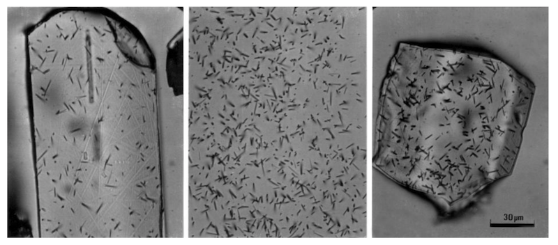
Figure 2.2: Etched fission tracks in (a) apatite, (b) muscovite and (c) zircon, all to same scale. (a) and (c) show spontaneous tracks, (b) induced.
In minerals the bulk etching rate is not uniform and varies in different crystallographic directions, so that the tracks take on different shapes, depending on which surface they are etched on. This is illustrated in Figure 2.3a, which shows the appearance of tracks on different surfce on a hexagonal crystal of apatite. Tracks etched on a basal surface (0001), normal to the c-axis, take the form of a hexagonal pyramid with a narrow tail, the tail showing the direction of the track. On a prismatic surface (e.g. 1000), parallel to the c-axis, the tracks are narrow and nearly parallel-sided with a narrow hexagonal cross-section, showing that the bulk etching rate parallel to the c-axis is greater than that across it. This anisotropic etcing means that the tracks take different shapes from needle-like to flattened, depending on the orientation of the particular track. The etched tracks are actually faceted, rather like negative crystals, although this form is usually not resolved for normally etched tracks due to the limited resolution of an optical microscope. Under a scanning electron microscope the polygonal cross section of the tracks can easily be seen (Figure 2.3b). Tracks on surfaces parallel to the c-axis are preferred for fission track analysis.
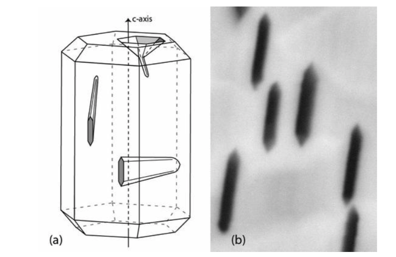
Figure 2.3: The shape of etched fission tracks on different crystallographic surfaces in a hexagonal apatite crystal. (a) shows the shape of tracks on surfaces normal to, and parallel to the c-axis, and (b) shows the shape of track etch pits on a c-parallel surface under a Scanning Electron Microscope (the etch pits are ~ 1.5 μm long). The narrow hexagonal outline of the anisotropically etched tracks can clearly be seen.
If etching is prolonged in crystalline materials, after the tracks have been revealed, the pits continue to enlarge and take on shapes controlled by the crystal symmetry. Figure 2.4 shows the etch pits which result from prolonged etching on basal surfaces in muscovite and apatite, and on any surface in glass. For tracks on the (001) cleavage plane in muscovite, the tracks remain parallel-sided but take on a rhombic cross section with continued etching. Very similar etch pits result when tracks on the (110) cleavage plane in zircon are over- etched as shown in Figure 2.5. Etching tracks on a basal surface of apatite produces pits of a quite different form as shown in Figure 2.4(b). These tracks develop as broad hexagonal pyramids having a narrow tail. With continued etching each pit grows until the end of the track is reached and a flat-bottomed hexagonal pit is produced. Similar tailed pyramids are also found on surfaces at high angles to the c-axis in zircon and on some orientations in sphene. Tracks on surfaces parallel to the c-axis in apatite and zircon appear like those in muscovite (Figure 2.2).
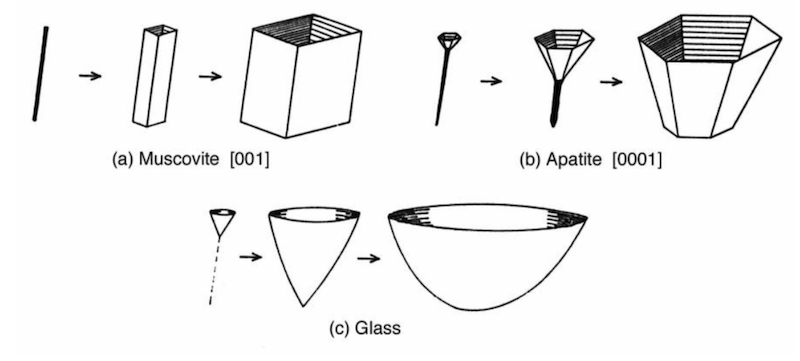
Figure 2.4: The shape of etch pits which result from prolonged etching of fission tracks in different materials.
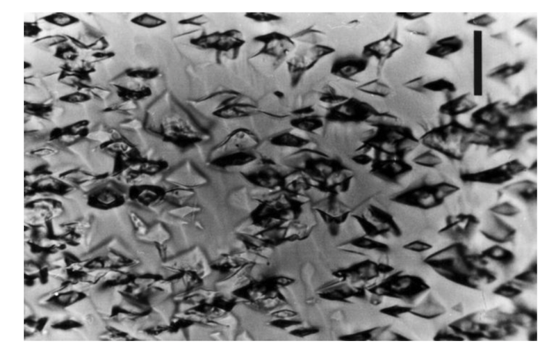
Figure 2.5: Strongly over-etched spontaneous fission tracks in zircon, after 60 hours in molten K0H-NaOH eutectic at 220°C. Surface shown is parallel to c-axis and (110) cleavage plane. Scale bar is 10 μm.
In glasses, fission tracks have a circular or elliptical cross-sections, even after prolonged etching, because the host material etches isotropically. Overetching simply produces broad, rounded and flat-bottomed pits as shown in Figure 2.4(c). These broad pits become difficult to distinguish from spurious etch features and usually only those pits which have a sharp conical apex can be unambiguously identified as tracks.
The simple description of track etching in terms of \(V_T\) and \(V_G\) has proved extremely successful in explaining track etching behaviour in isotropic materials such as glasses and plastics. But, as can already be seen from the changes in track shape during prolonged etching, the etching of minerals is more complicated. There are two important factors that contribute to this complexity in minerals. First, \(V_G\) is anisotropic in most minerals, and second, this anisotropy is progressively reduced by accumulating radiation damage from the alpha-decay of U and Th in the host mineral (Gleadow 1978).
When the general etching rate, \(V_G\), of a material is anisotropic, the etching efficiency will still be high where \(V_T\) is much greater than the value of \(V_G\) normal to the surface. The track cross-section, however, will be controlled by variations in \(V_G\) in other directions as illustrated in Figure 2.6. Within the plane of the etched surface the anisotropic etching rates are described in terms of two different components \(V_{G1}\) and \(V_{G2}\). The size and shape of the two tracks are quite different and so is their visibility after normal etching conditions. Some tracks have the shape of knife blades so that their visibility will in part depend on the direction from which they are viewed. In some cases of extreme anisotropic etching, such as in young sphenes, tracks in certain orientations may be so weakly developed as to be invisible under normal etching and observing conditions.
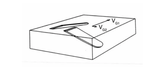
Figure 2.6: Etching of fission tracks in an anisotropic mineral with fast (\(V_G1\)) and slow (\(V_G2\) bulk etching velocities in the plane of the etched surface.
This can be seen more clearly in Figure 2.7(a), which is a vertical projection of the same tracks. The width of the narrow (edge-on) tracks may be too small to be resolved under the microscope even though the broad track may be quite plainly visible. This gives rise to an apparently anisotropic distribution of track orientations. The different degree of etching achieved by tracks in different orientations in a fresh sphene crystal can be seen in Figure 2.8(a). It is possible, or even probable, that \(V_T\) is also anisotropic in many minerals so that the etching efficiency could also vary from track to track according to their orientations.
Another consequence of anisotropic etching is that some crystallographic planes will have a much higher \(V_G\) normal to the surface, and hence a lower etching efficiency than other surfaces. The extreme example of this is with zircon etched in the usual eutectic KOH-NaOH etchant where the etching efficiency varies from essentially 100% on surfaces parallel to the c-axis to zero on basal surfaces (Naeser et al. 1980). It is obviously critical in such minerals that surfaces with the highest etching efficiency be selected for counting. Fortunately, there is a simple way of identifying the surfaces that have the lowest values of \(V_G\), and therefore the highest etching efficiencies. This depends on the appearance of minute polishing scratches that are inevitably present after etching on even the best polished surfaces. The sharper the polishing scratches, the lower is the surface etching rate. Selecting for counting only those surfaces where the polishing scratches are less than about 1.5 μm across will ensure the highest (approx. 100%) etching efficiency (Gleadow 1978, 1981).
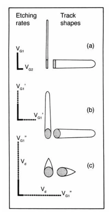
Figure 2.7: Three different stages of fission track etching during the ageing of an anisotropic mineral. (a) Shows the etching of fission tracks in the fresh (or annealed) anisotropic mineral. (b) Over the geological lifetime of the mineral alpha-recoil damage accumulates and modifies the initially anisotropic etching properties. The damage has an isotropic etching rate, \(V_d\), which is added equally to the original etching velocities. (c) Eventually so much radiation damage has been formed that the mineral has a very high bulk etching rate in all directions and behaves like a glass in its track etching properties. This stage is only reached when the mineral is virtually metamict.
As a uranium-bearing mineral ages, it accumulates not only fission tracks but also radiation damage from the alpha-decay of the uranium and any thorium present. The alpha-decay occurs at a much greater rate so that for every spontaneous fission event there are more than two million alpha events. This process may eventually lead to the metamict state that is thought to largely reflect the alpha- recoil damage. In some minerals, notably zircon and sphene, this accumulating radiation damage has a major effect on the fission track etching properties. Apatite, in contrast, has never been observed in the metamict state.
The most obvious change caused by this damage is a dramatic reduction in the time taken to etch the tracks with increasing track density, as shown in Figure 2.8 for sphene and zircon. This change in etching rate with radiation damage tends to accentuate any uranium zoning which is quite common in zircon and sphene. This can be seen in Figure 2.8(b) that shows a zoned sphene crystal, the adjacent zones varying from underetched to overetched depending on the track density. No such relationship has ever been observed for apatite, however, which is thought to reflect a low stability for the alpha-related damage in this mineral, so that it does not accumulate over geological time. It is significant in this regard that apatite has never been observed in the metamict state, unlike both zircon and sphene.
As the level of radiation damage increases, in sphene and zircon, the initially anisotropic etching properties are modified so that the mineral behaves more like an isotropic mineral. This stage of track etching is illustrated in Figure 2.7(b). The recoil damage probably occurs as small zones of rapidly etchable and essentially isotropic material distributed throughout the mineral. The etching rate, \(V_d\) of this damaged material is added to both \(V_{G1}\) and \(V_{G2}\), so that the total bulk-etching rate in each direction is now much more uniform. As more radiation damage is added the etching properties of tracks in different orientations will become progressively more isotropic. The track cross-sections will also change as the crystal structure is degraded, so that the common rectangular or rhombic shapes are replaced by more rounded forms.
In the extreme case, Figure 2.7(c), so much radiation damage is added that the general etching rate becomes essentially uniform in all directions. The mineral is then approaching the metamict state and behaves rather like a glass, with a low etching efficiency and broad track cone angle. Such glass-like tracks in a near-metamict sphene are shown in Figure 2.8(c). Fortunately, this extreme effect of radiation damage on track etching is only reached when the track density is already at the limit for optical counting (above \(2 \times 10^{7} cm^{-2}\)).
Anisotropic etching and accumulated radiation damage can have important implications for fission track dating methods that have been discussed in detail by Gleadow (1981). The most important considerations are to ensure that all tracks have been sufficiently etched by a given etching treatment and that they have been revealed with the maximum etching efficiency. In highly anisotropic materials (low damage levels) tracks in some orientations may have a low etching efficiency or at least be so weakly developed that they will be overlooked.

Figure 2.8: Etching of sphenes at the three stages shown schematically in Figure 2.7(a) Shows the highly anisotropic etching of induced tracks in an annealed sphene, etched 25 min in the mixed acid etch (Table 2.1). (b) Shows the less anisotropic but very variable etching at intermediate damage levels in a zoned sphene, ranging from underetched in low-U zones, to strongly overetched and unresolvable in the highest-U core zone (etched 12 min). (c) Shows the small rounded, conical etch pits, resembling tracks in glass, found in a sphene with an extreme track density of about \(8 x 10^{7} cm^{-2} and etched 1 min. The scale bar is 20 μm in each case.
Tracks become visible during chemical etching as they are enlarged to a point where they can be resolved under an optical microscope. It follows that there is some minimum etching time, which must be exceeded before all the tracks will be large enough to be visible. Underetched tracks are faint and difficult to see so that the track density will be underestimated. On the other hand, overetched tracks like those described above, are difficult to discriminate reliably from other etch features, and even from each other if the track density is high e.g. Figure 2.5. Ideally, therefore, tracks should be etched to somewhere between these two extremes for reliable counting and identification.
In cases where \(V_G\) normal to the surface is relatively high, such as in glasses and some orientations in crystals, new tracks will be exposed as etching proceeds due to the gradual lowering of the surface. It is therefore extremely important to establish etching conditions that give a stable track density that is insensitive to minor variations in those conditions. In glasses, where \(V_G\) is high, the total number of etch pits simply continues to increase with increasing etching time. The rate at which this increase in track density occurs may be described by a 'prolonged etching factor' (Khan and Durrani 1972). A simpler way of obtaining a stable track density in glasses, however, is to count only sharp-bottomed conical etch pits and to ignore all flat-bottomed rounded pits which have been enlarged beyond the end of the original track.

Figure 2.9: The relationship between etching time and track density in (a) sphene, etched in a mixed acid etch at 20°C (Table 2.1) and (b) zircon etched in eutectic KOH-NaOH (Gleadow et al. 1976). Etching time for spontaneous tracks decreases rapidly with increasing track density in both minerals but induced or implanted tracks in an annealed sphene show no change. X-ray powder patterns for three of the sphenes show the peak degradation accompanying incipient metamictization.
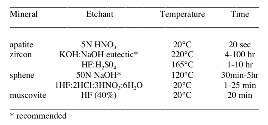
Table 2.1: Etching conditions for common FTD minerals
The way in which track density varies with etching time in minerals is illustrated in Figure 2.10. It can be seen that for each of the four minerals, the observed track density rises relatively rapidly to a plateau value which is maintained during further etching. The minimum acceptable etching time, \(E_{min}\) is the time taken to reach the beginning of the plateau. The appearance of the tracks in sphene and zircon after each etching treatment is shown in Figure. 2.11 and 2.12. These may be used to judge when tracks in an unknown sample have been adequately etched. The optimum etching time is usually about 1.5 to 2 times \(E_{min}\) for a particular mineral sample, giving tracks approximately 1 μm in diameter. An extremely useful exercise for a novice in fission track studies is to carry out just such a progressive etching experiment to gain direct experience of the appearance of tracks which are adequately etched. The correct etching time in minerals such as zircon and sphene, is highly variable and will depend on a variety of factors, especially the general radiation damage level. It is extremely important in these minerals that the degree of etching be judged from the appearance of the tracks and not from the application of some standard etching time. Apatite is more consistent in its etching behaviour and a standard etching time can often be used, although exceptions will be found from time to time.

Figure 2.10: Variation of track density with etching time for spontaneous tracks on internal surfaces of (a) apatite, (b) zircon and (c) sphene, and induced tracks in a muscovite external detector (d). Etching conditions as in Table 2.1 (acid etchant for sphene), except for zircon which used a 100N NaOH etchant.
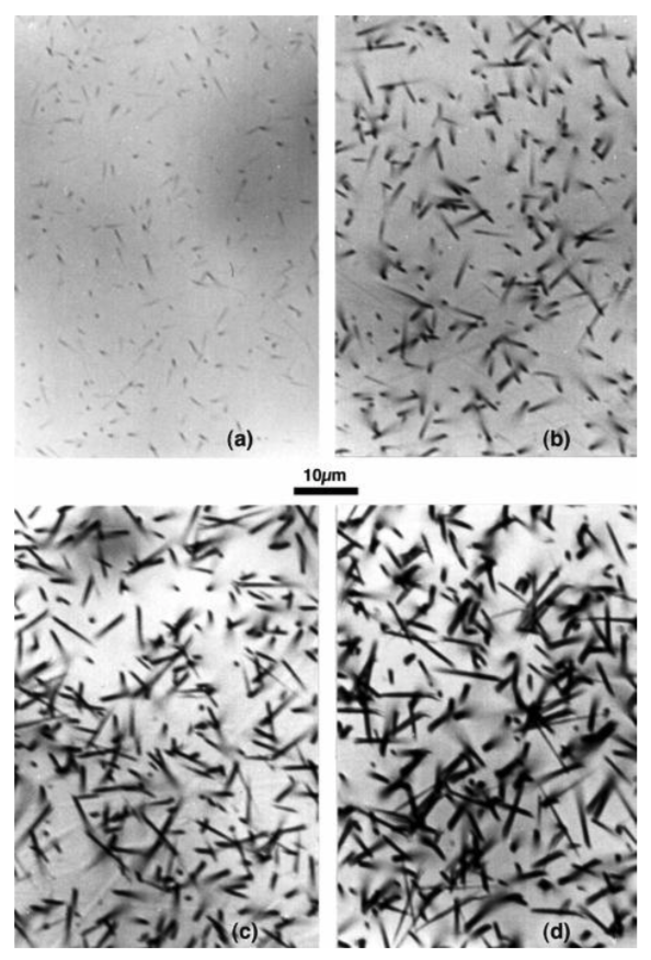
Figure 2.11: The appearance of spontaneous tracks in sphene after various etching times. (a) to (d) show tracks etched for 5, 10, 15 and 20 minutes respectively in the acid etchant (Table 2.1). The tracks in (b) represent the minimum degree of etching (\(E_{min}\)) for which a reliable track density is obtained.

Figure 2.12: The appearance of spontaneous tracks in zircon after 2.5, 3.75, 5 and 6.25 hours in 100N NaOH at 270°C; (a) to (d) respectively. Again the tracks in (b) represent the minimum acceptable degree of etching for reliable counting.
Various other etchant parameters, such as temperature and concentration, can also have an important influence on track etching. Table 2.1 shows the most commonly used etching conditions for different minerals and glasses. For both sphene and zircon when using hydroxide etches, for instance, raising the temperature tends to increase \(V_G\) of the surface, relative to \(V_T\), leading to an increase in track cone angle and a reduction in etching efficiency. To some extent a similar effect may be observed in apatite due to etchant concentration. Apatites etched in concentrated HNO3 have a higher track cone angle than do those etched for longer times with more dilute concentrations. The particular choice of etchant used is also important in many cases. The anisotropic etching characteristics of both zircon and sphene are significantly greater when using the acid etchants listed in Table 2.1 than for the hydroxide etchants. This can be seen in Figure 2.13, which shows the same zircon etched in a hydroxide and an acid etchant for comparison. Except where the radiation damage levels are fairly high, therefore, the hydroxide etchants are to be preferred and give better results for both these minerals.
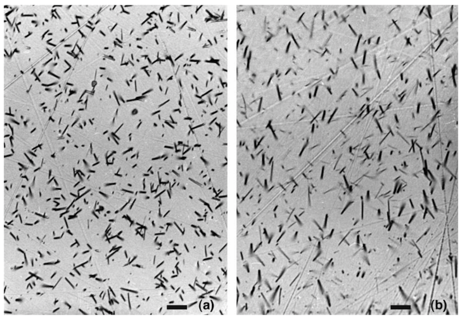
Figure 2.13: Spontaneous fission tracks in zircon from the Mud Tank Carbonatite in Central Australia etched in (a) the \(KOH:NaOH\) eutectic etchant of Gleadow et al. (1976), and (b) in the equivolume \(HF:H_{2}SO_{4}\) etchant of Krishnaswami et al. (1974). The eutectic etchant has revealed the tracks more isotropically than the acid etchant. The polished surface is parallel to the (110) cleavage and the extended feint lines running across each frame are polishing scratches. The scale bar on each frame is approximately 10 μm.